Ice buildup on the evaporator can significantly reduce system performance and cooling capacity. Traditionally, defrosts have been based on fixed schedules, leading to unnecessary defrosts during periods of low humidity. Our Defrost Sensor, provides a flexible solution for automatic defrosting, initiating the process only when necessary.
Features and benefits
Below, you can find various materials relevant to this product category.
• Defrost on demand
• Defrost calculator
• The importance of defrosting
• YouTube channel with different videos
Want to know more?
>>Click here and get in touch for price and delivery
Not sure which Defrost Sensor version to choose? Click the button below to see our selection guide.
|
Version |
Temperature range |
Features |
|
Low temperature freezers (HBDF-LT) |
-60°C to 0°C (-76°F to 32°F) |
With insulation for low temperatures |
|
Normal freezers (HBDF-Freezer) |
-30°C to 0°C (-22°F to 32°F) |
Standard version |
|
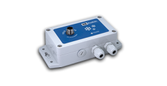
Cold room (HBDF) |
-30°C to 10°C (-22°F to 50°F) |
Include temperature sensor |
|
Heat pump (HBDF-OD) |
-60°C to 20°C (-76°F to 68°F) |
Special product for OEM |
Application: Freezer -30°C to 10°C
Product code: HBDF
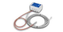
Application: Heat pumps
Product code: HBDF-OD
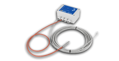
Application: Freezer -30°C to 0°C
Product code: HBDF-Freezer
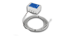
Application: Freezer -60°C to 0°C
Product code: HBDF-LT
Output: 4-20 mA
Measurng: Ice up to 100 mm
Product code: HBIB-MK2-5