Technical data: HBLT-C1
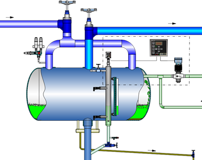
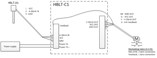
The HBLT-C1 is a programmable controller designed for level control in industrial refrigeration systems. It is compatible with a range of analog level sensors, such as the HBLT-A1 and HBLC-CO2, or other sensors that output a 4-20 mA signal. This flexibility allows it to integrate seamlessly into various industrial refrigeration applications.
Key features
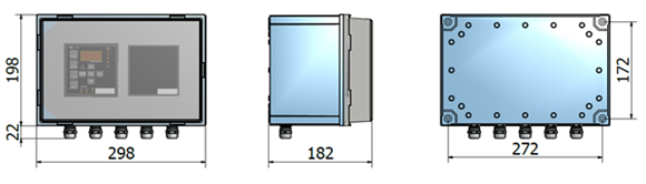
- Power supply: The controller operates on a 24 V DC power supply.
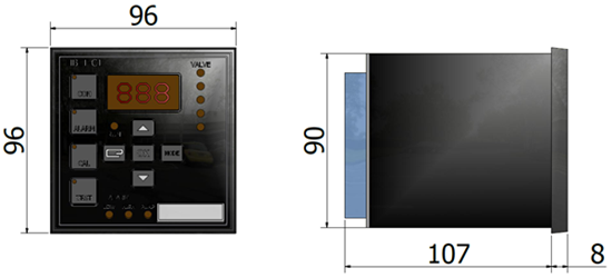
- LED indicators: Provides clear visual indicators for power supply and alarm status.
![]()